5 SolidPlant tools that make Plant Design easier
In today’s plant design industry, it’s all about efficiency. No design company wants to waste valuable time on parts of the design process if there are easy solutions available to save that precious time. SolidPlant has many tools that make Plant Design easier and thus faster. In this article, the focus will be on the five most eye-catching.
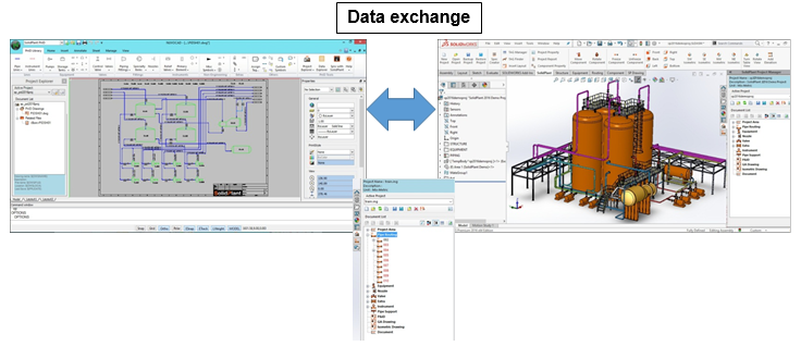
1. Bi-direction
BI-Direction is a rare function in Plant Design software. It’s a great way of making sure that the data of the P&ID and the 3D model of the same project stays in correspondence with each other. It works like this: Upon opening the P&ID software, you will be notified when a change has been made in the 3D model of the same project. It also works the other way around when opening the 3D project after a change was made in the P&ID. This function is very useful, because you don’t have to waste time checking data between the P&ID and the 3D model.
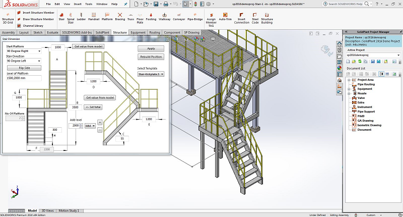
2. Steel Structure
SolidPlant offers an amazing tool for generating various types of Steel Structures, all in compliance with international standards, such as ANSI, AS, BSI, CISC, DIN, GB, ISO, JIS, etc. Based on only a single sketch line, the software generates a 3D model of any desired part in a typical plant structure. Some examples are:
Stair model : With the stair model, SolidPlant offers the user the freedom of setting dimensions, number of platforms, angle of stairs, orientation, number of supports, while still maintaining the ease of use and the high speed of model generation. A spiral staircase is also available.
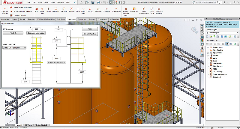
Ladder model : Just like the stair model, the ladder model in SolidPlant is based on a template which allows for easy adjustment of properties. The user has the possibility to add a cage for extra safety.
Just like the stair model, the ladder model in SolidPlant is based on a template which allows for easy adjustment of properties. The user has the possibility to add a cage for extra safety.
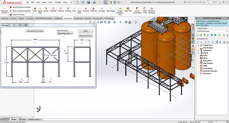
Pipe-Bridge model : A pipe-bridge can be created very quickly with the designated template, which can be expanded with additional levels.
Apart from the models listed above, SolidPlant provides additional models for handrail, platform, bracing, truss, walkway, floor plate and conveyor.
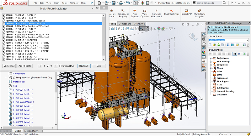
3. Multi-Route Navigator
Multi-Route Navigator is a great tool to help navigate multiple pipe preview lines. If you want to see how a number of pipe lines relate to each other, but don’t want to spend a lot of time drawing each one of them, Multi-Route Navigator is the way to go. With just a few clicks, the software will generate center lines of any number of lines in the project. After that, the lines can be customized and converted into 3D pipes. This tool is especially useful in the conceptual design stage of a project.
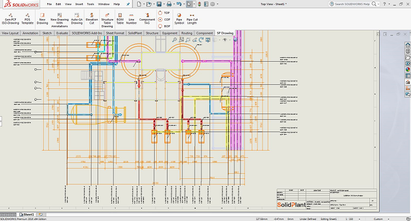
4. Auto GA
Auto GA allows for automatic generation of the General Arrangement Drawing. The user can choose from a wide range of data to be featured in the GA drawing: section, elevation, views, line numbers, tags, TOP, COP, etc. Just select which of this data must be included and SolidPlant generates the drawing with all its annotations, greatly reducing the time spent on this part of the design.
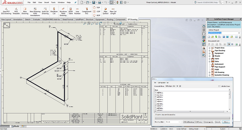
5. Gen-PCF & ISO-Drawing
Gen-PCF & ISO-Drawing is another exceptional tool to quickly produce output d documents. SolidPlant has embedded the Isometric Drawing Software ISOGEN, which is the industry standard, into its package. With only a single click, SolidPlant generates the Isometric Drawing with optional Bill of Material included in the drawing. In the same way, SolidPlant produces PCF files for pipe stress analysis, which can be exported to relevant software like AutoPIPE, Ceasar II and ROHR2.
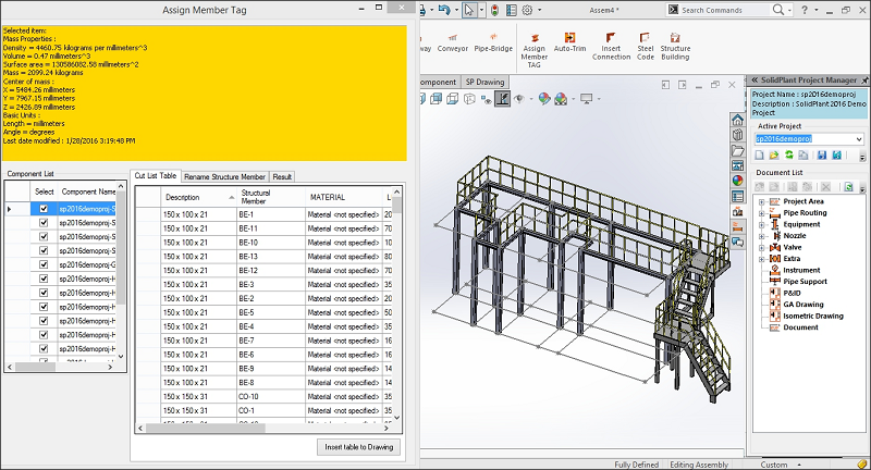
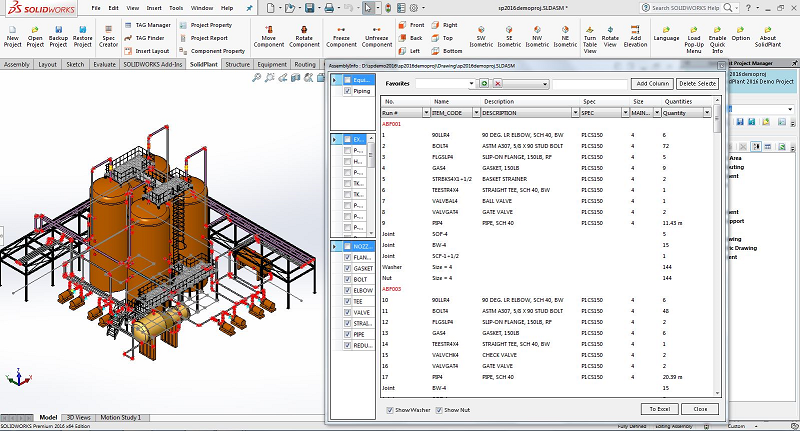
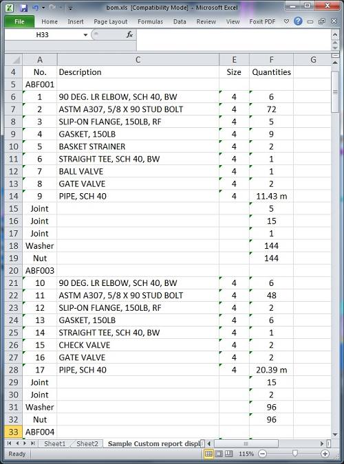
6.MEMBER LIST & REPORT
SolidPlant has the possibility to produce project reports of the Steel Structure, Equipment, Nozzle, Pipe and components. They come directly from the 3D models and are available the file formats of MS Excel (* .xls and * .xlsx).