


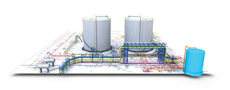
SolidPlant 3D 2016
Comprehensive Plant Design for SolidWorks
What’s new? Feature highlights.
The latest comprehensive plant design for SolidWorks.
Fully compliant with SolidWorks 2016. We proudly present 3 major features.
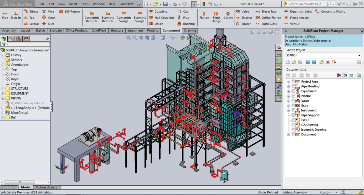
- Multi route navigator
This advanced feature is very unique. The user will be prevented from making mistakes that put the wrong pipeline into the wrong place.This feature also gives the user the ability to see the big picture of the entire pipeline system that would be placed in the model. With just a single click you will get a preview of every pipeline in the plant you are designing by automatically retrieving the data from the P&ID drawing.
You may even move around the equipment or structure to have a better vision of how the pipe will be routed. Save huge amounts of time, make fewer mistakes and be surprised by how easy it is to use.
- AutoGA (General Arrangement Drawing)
This cutting-edge feature will save lots of time when creating the GA drawing. SolidPlant AutoGA will generate 2D GA drawing automatically with complete dimensions and other necessary information. All of which is also fully customizable.
- Bi-directional updating
The most wanted feature of all time is now available on SolidPlant 2016. 3D model and P&ID data is now synchronized. Whether you add, delete or edit something in the 3D model, the program will prompt an alert on the P&ID side once you reload the project.
The same principle goes the other way around: You will be alerted in the 3D model when you change the P&ID data.
User Interface improvement (UI) : Our new Tag manager panel will allow you to search and find exactly where the components have been placed in the 3D model. Also the user can (do) place mouse over any equipment or component. all the information will pop up automatically. This is just to make sure that you are working on the right one.
Create your own 3D component (Custom) : SolidPlant 2016 will allow you to add your own catalog and your own 3D model into the database easily. Then you can work exactly on your standards every day.
New Conveyor template (Conveyor) : New conveyor template has been added. Easy and quick as usual.
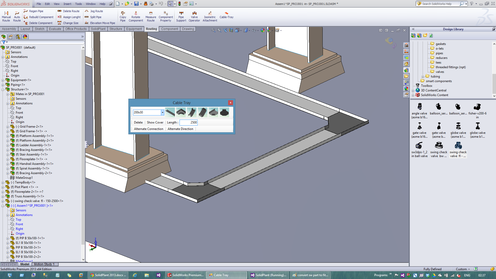
DUCT/Cable tray (DUCT) : New Autoroute feature for non-round piping will let the user do the DUCT and Cable tray much faster and with much more flexibility.
Assign project area
User can add project area to all equipment models. This will help the user to have a better view and control over a big project.
Drag & Drop from Tag number to model
Once the 3D model has been created, the tag number will turn to blue color. Then we can click on the Tag number and drag it to 3D model space. The 3D model of that tag number represented will be put in place.
Engine change
Fully Supports SolidWorks 2016 x64 bits. Central database has been changed to SQL server. This will speed up the whole system and support bigger projects.
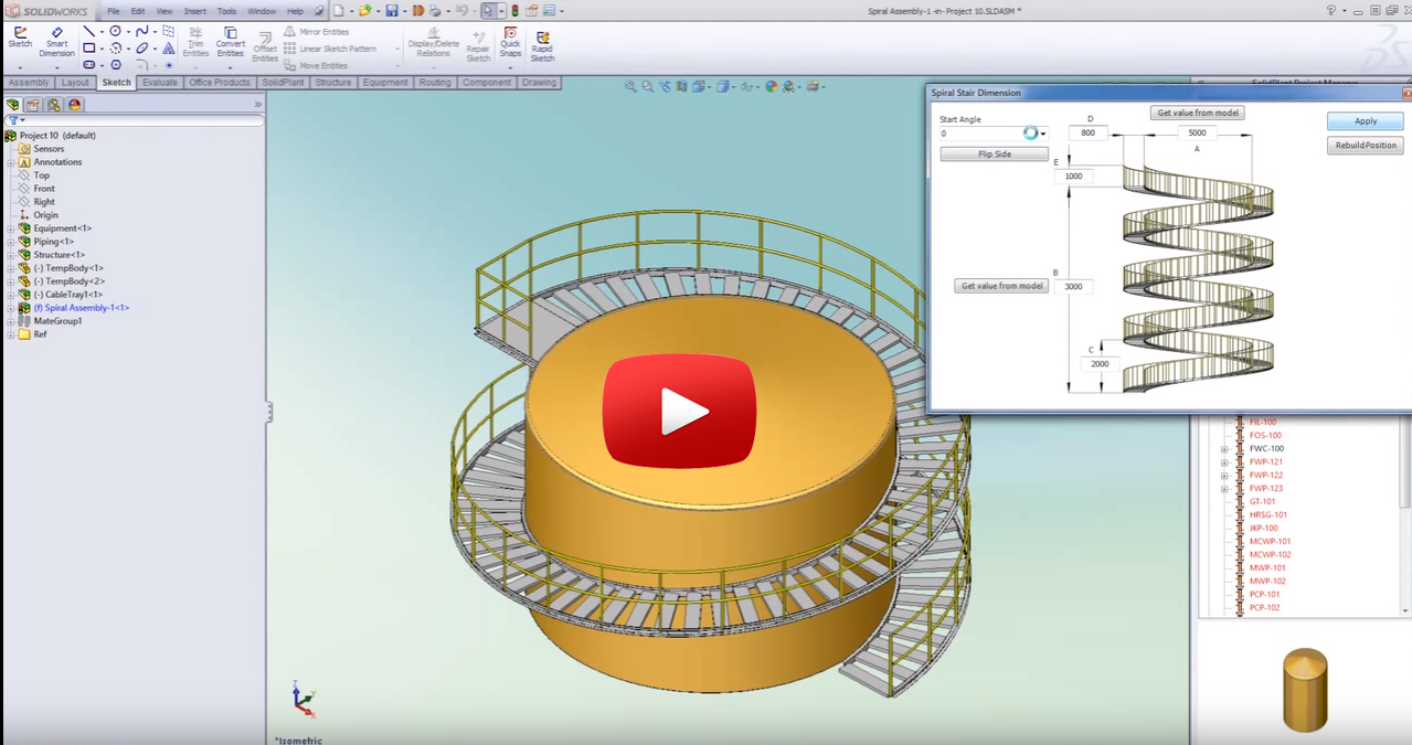
Spiral stairs
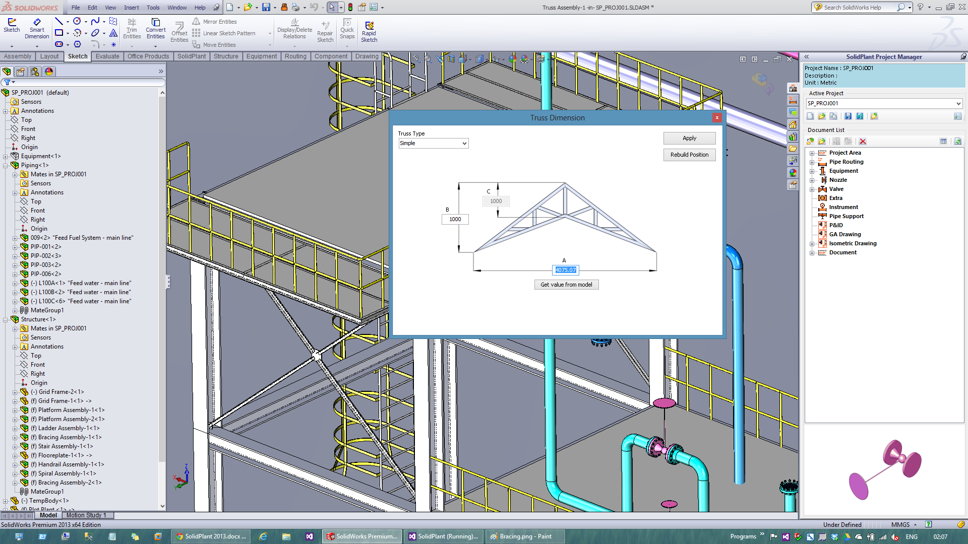
Truss
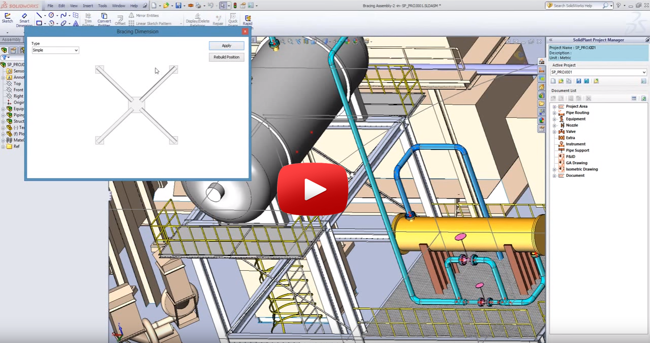
Bracing
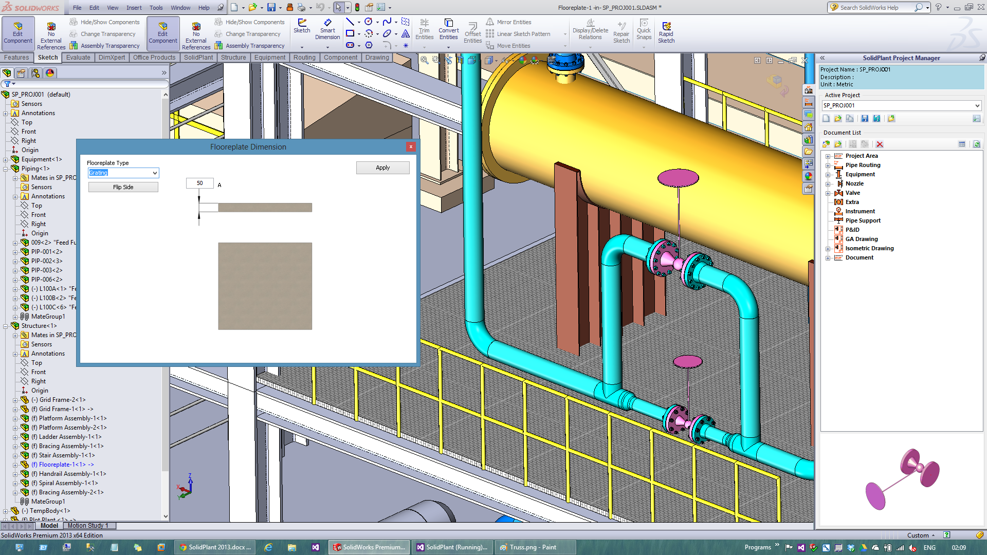
Insert Texture to the floor plate. To give you better presentation
Show/Hide nozzle tag number
Very important to have a view during routing which exact nozzle we are working on
Assign Nozzle length
Now we are able to assign the length of all nozzles when creating equipment either from templates or imported models.
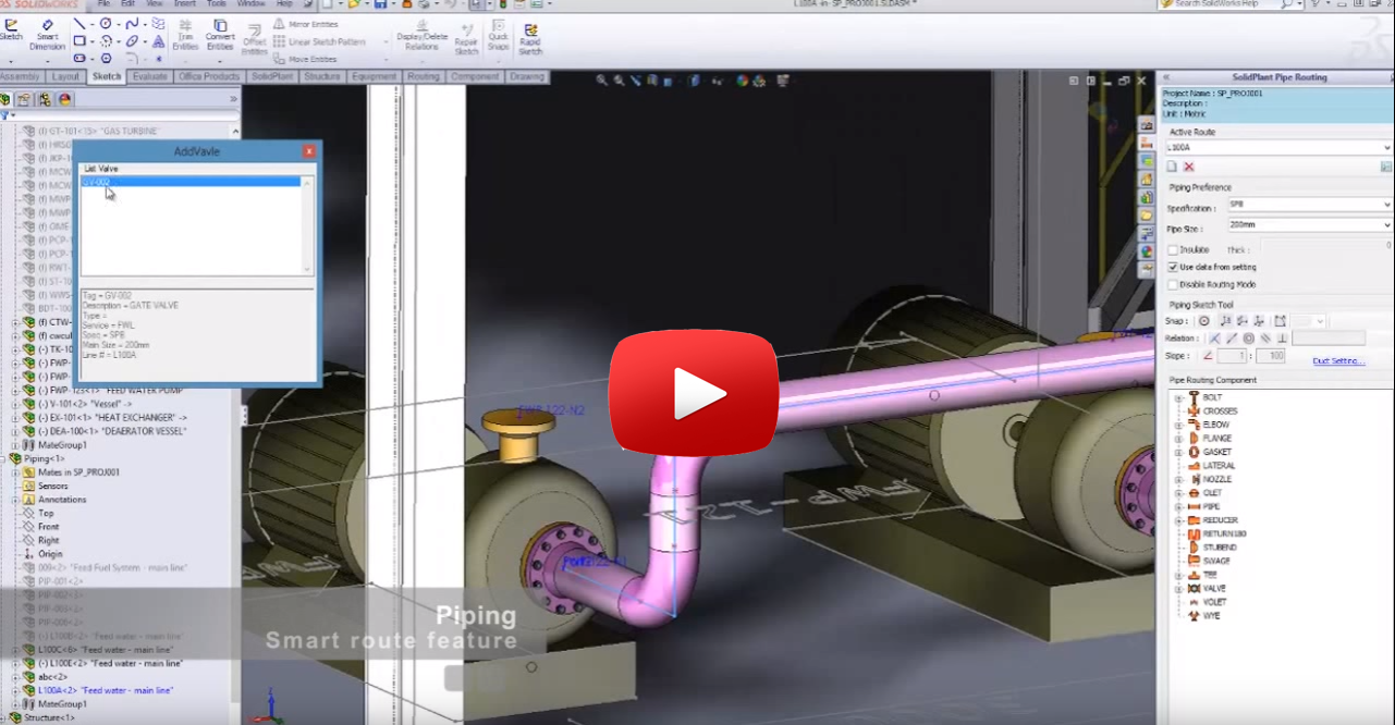
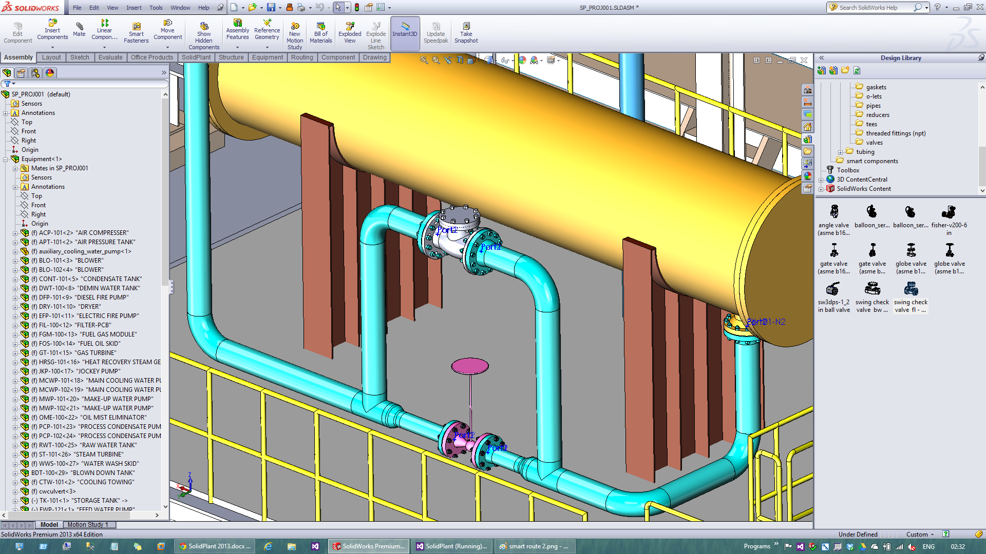
Smart route feature
The latest smart feature from SolidPlant. Now we don’t need to worry about routing to the wrong nozzle. SolidPlant will use the data from line list. Which contains the from-to nozzle number information to create automatic route line from nozzle to nozzle with the shortest route path. The user will be allowed to modify the route by cut, extend, trim or other sketch tools that are provided by Solidworks until we get the best route path. Easy and flexible.
Related Valve automaticly assigned
From the valve list data, SolidPlant will let pop up all the valves that are related to the pipe line number that the user just finished routing. We can drag and drop from the list on the pipe automatically. You will never miss the valve or put it to the wrong line number.
Show/Modified line number during routing
Convert existing part to pipe components
We can convert any old part model if we wish to use it in the new project as a pipeline of another project
Automatic Bushing
Insert and Information check of Flanged fitting
We can add flange fitting and check the data from it such as schedule or rating.
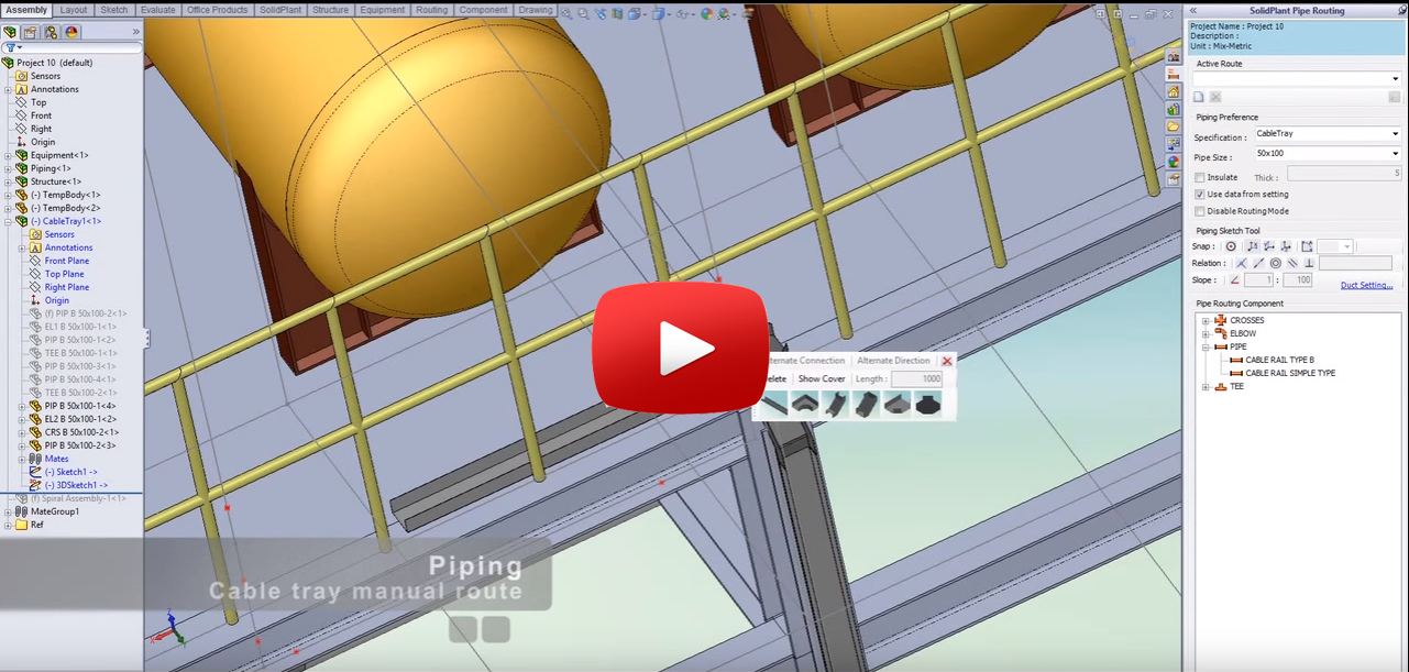
Cable tray manual route
With a simple draw panel, Now we can draw 3D cable tray by continuing one by one part. The connection can change the direction by toggle the tab button.
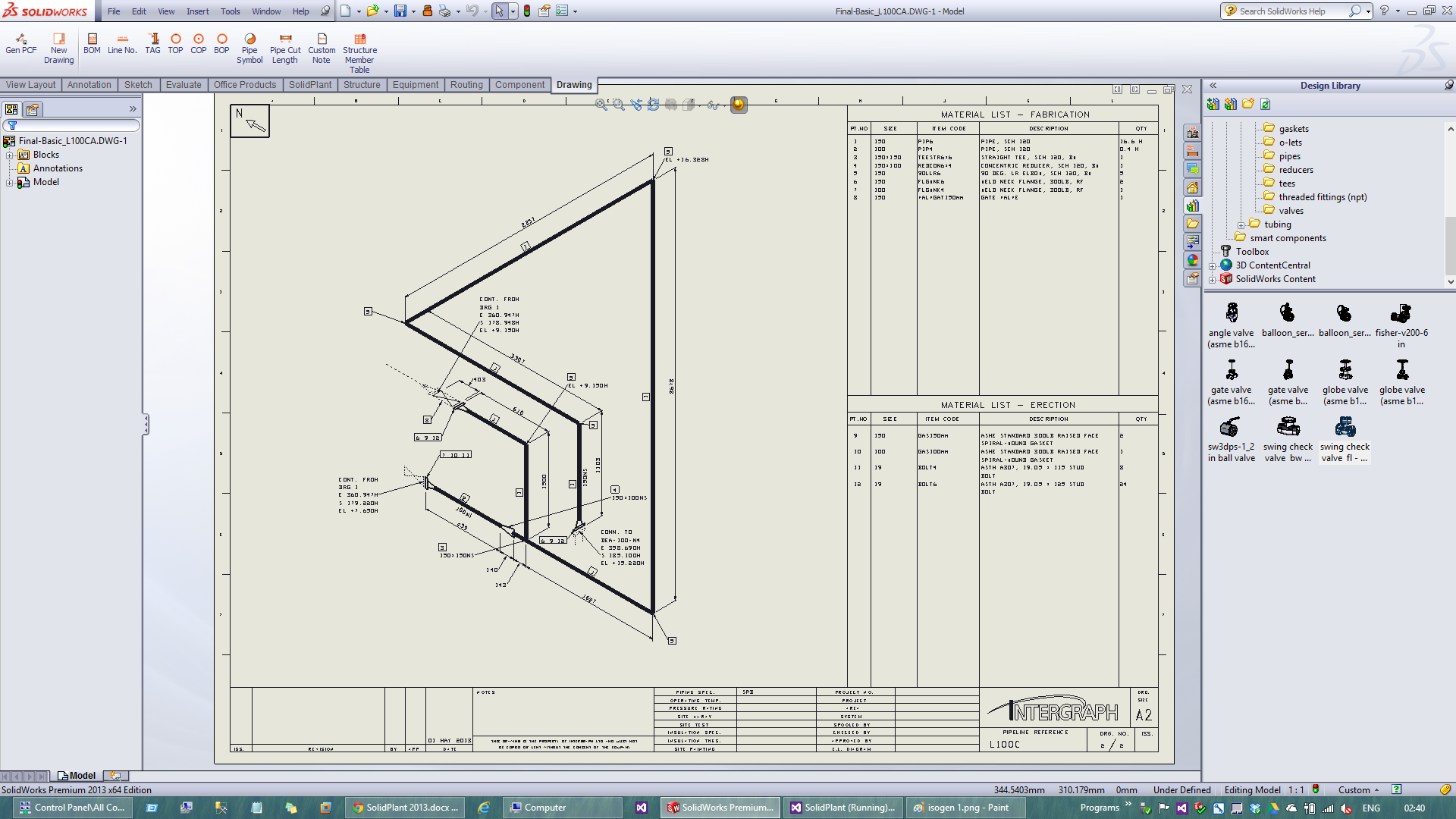
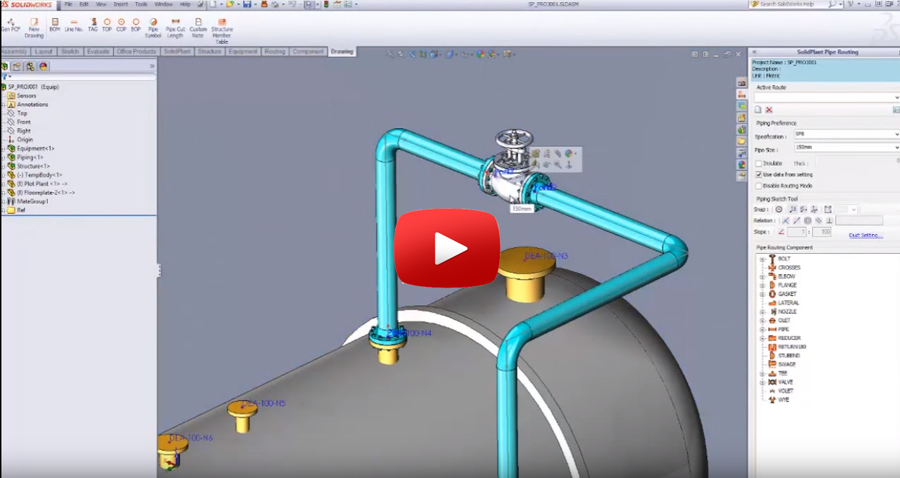
Import PCF file format to generate Iso drawing.
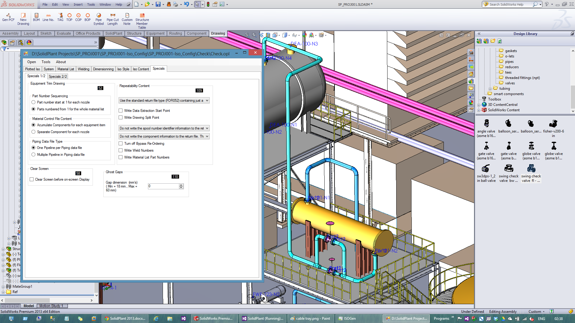
New Isogen option switch interface
Ease of use pop up menu for option switch.
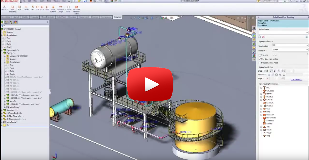
Isogen Video
SolidPlant 3D Demo Videos
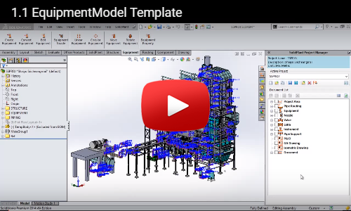
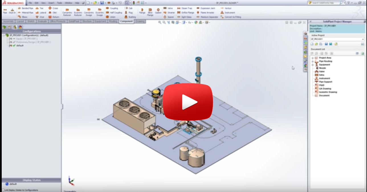
Create Equipment : Create equipment using SolidPlant templates.
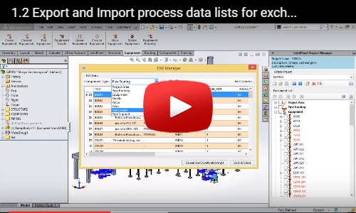
Import PID Data : Import P&ID data for use in Piping and Equipment design.
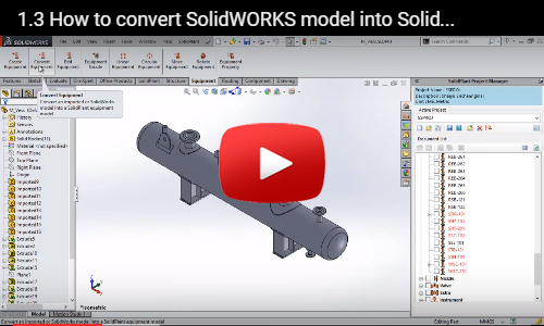
Convert Equipment : Convert existing CAD models into SolidPlant Equipment models.
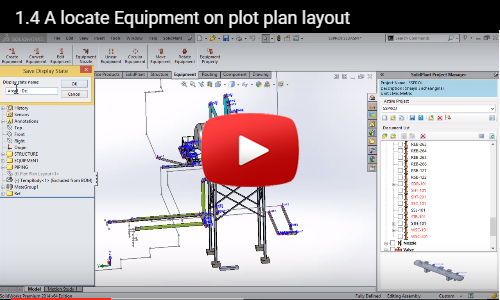
Place Equipment : Drag Equipment models into the plant and locate them using move functions.